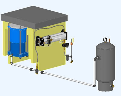
Plumbing for high pressure die cushions
(models HC, HD and HMC) includes the following components:
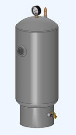
- Surge Tank with gauge, pop safety valve and drain cock
- Reducing Regulating Valve and Pressure Gauge
- System Drain Cock
All plumbing components used should be rated to the working air pressure
of at least 300 psi for high pressure die cushions. Special attention
should be given to make sure that plumbing is free of metal shavings
and other debris (for example from threading pipes) that can get inside
the die cushion piston-cylinder wall and destroy the bearing surface.
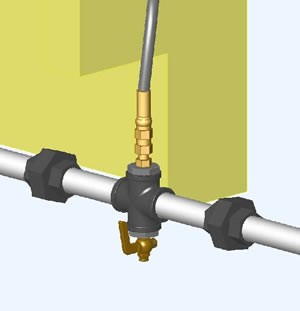
Die Cushion surge port is connected to the surge tank using pipe or
hose assembly. At the convenient point outside the press bed, cross
should be installed that gives additional two input/output points
into the plumbing for shop air input line (through the booster pump)
and system drain line. |
|
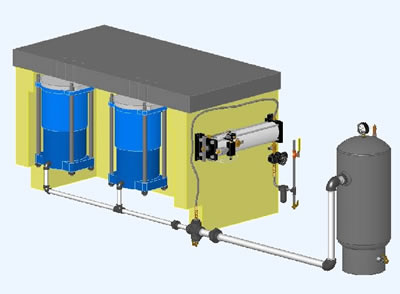
When two or more cushions are installed in the same
bed, they can be either tied into one air system or have independent
air systems. Die cushions have to be under one air system if they
have common pin pad or if the uniform system pressure has to be achieved
between independent cushions.
If they have separate air systems, cushion pressures can be set differently
thus achieving different tonnages. In such case general instructions
for single cushion plumbing should be followed. As an option connecting
line can be added in between surge tanks for each of the cushions
with the ball valve. When the valve is closed each cushion will have
different pressure, once opened valve will allow for uniform pressure
in all of the cushions connected.
When multiple cushions are connected to one surge tank, the surge
line size should increase as they join into one line (it is discussed
later in this section). |
|
| Surge port is located either in the back
or on the side of the die cushion piston flange. Depending on the
installation, it can be also drilled in the bottom of the piston,
if space inside the press bed is limited. All cushion units are drilled
and tapped for the correct size surge line to handle the flow of air
required. On multiple units installations a reducing bushing for the
correct size is furnished to give the proper air flow for the entire
installation. The pipe sizes given below are the recommended sizes
for cushion installation consisting of one to six cushion units connected
together. |
Surge Port Size |
|
Cushion Model & Size |
Number of Cushions |
1 |
2 |
3 |
4 |
5 |
6 |
| HC8 & HD8 |
1/2 |
3/4 |
1 1/4 |
1 1/4 |
1 1/4 |
1 1/2 |
HC10 & HD10 |
3/4 |
1 1/4 |
1 1/2 |
2 |
2 |
2 |
HC12 & HD12 |
3/4 |
1 1/4 |
1 1/2 |
2 |
2 |
2 |
HC14 & HD14 |
1 |
1 1/2 |
2 |
2 1/2 |
2 1/2 |
3 |
HC16 & HD16 |
1 1/4 |
2 |
2 1/2 |
3 |
3 |
X |
HC18 |
1 1/4 |
2 |
2 1/2 |
3 |
3 |
X |
HC20 |
1 1/4 |
2 |
2 1/2 |
3 |
3 |
X |
HC22 |
1 1/2 |
2 1/2 |
3 |
X |
X |
X |
HC24 |
1 1/2 |
2 1/2 |
3 |
X |
X |
X |
|
| Surge tank should be installed as close to the cushion
unit as possible to minimize the flow of air through surge lines.
The surge tank itself may be installed in either a horizontal or vertical
position as each surge tank has the required number of outlets to
make either of the installations. Surge tank should have the pop safety
valve, pressure gauge and drain cock installed. These components are
furnished with each die cushion. For easy access, street elbow, nipple
and coupling (1/4" NPT) can be installed on the bottom of the
tank and then drain cock can be attached to them. |
 |
Description |
Part Number |
Connection |
Pop Safety Valve 250 psi |
6308 |
1/2 NPT |
Pressure Gauge |
6114 |
1/4 NPT |
Surge Drain Cock |
443 |
1/4 NPT |
|
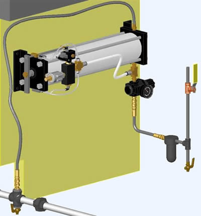
| Booster pump intensifies input shop air
pressure to achieve the maximum of 200 psi system pressure. The pump
can be mounted horizontally or vertically to the press frame or any
other convenient place by bolting through four holes provided in the
mounting structure. Select space large enough to accommodate pump.
If the pump is mounted on an uneven or curved surface, care should
be taken not to bend pump. Booster pump should be connected to shop
air line with standard pipe fittings (1/4" NPT) and to the cushion
using high pressure hoses through the cross as shown below. It is
also advisable to install a globe valve and air filter on the end
of the shop air pipe so that air pressure can be turned off when cushion
is not in use and only clean, free of debris air is delivered to the
die cushion. |
|
|
Description |
Part Number |
Connection Size |
Regulator Assembly |
1502 |
x |
Regulator |
3241 |
1/4 NPT |
Pressure Gauge |
284 |
1/4 NPT |
Vibration Dampers |
451 |
x |
| Hose Assembly |
3248 |
x |
3 ft Hose |
6310 |
1/4" |
6 ft Hose |
6309 |
1/4" |
Hose Adapters |
6313 |
1/4" NPT |
| Globe Valve |
Not Furnished |
x |
| Air Filter |
Not Furnished |
x |
|
| |
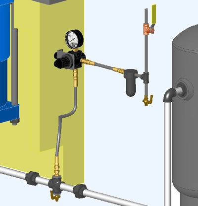
| System drain is important part of the die cushion plumbing.
It allows removing all accumulated moisture inside the die cushion
that can limit the surge volume and cause the increased system pressure
(above allowable levels) at the bottom of the working stroke. That
is why drain cocks should be opened regularly as a part of the die
cushion maintenance schedule. Usually die cushion installation should
have 2 drains installed, one at the low point of plumbing and the
other one directly on the tank. To create the entry port for the second
drain cock mentioned, cross and reducing bushing is shipped with die
cushion. It should be installed outside the press so that there is
easy access to the drain cock. The other open port on the cross should
be used to connect high pressure hose from the regulator. |
|